Compound Parabolic Concentrators
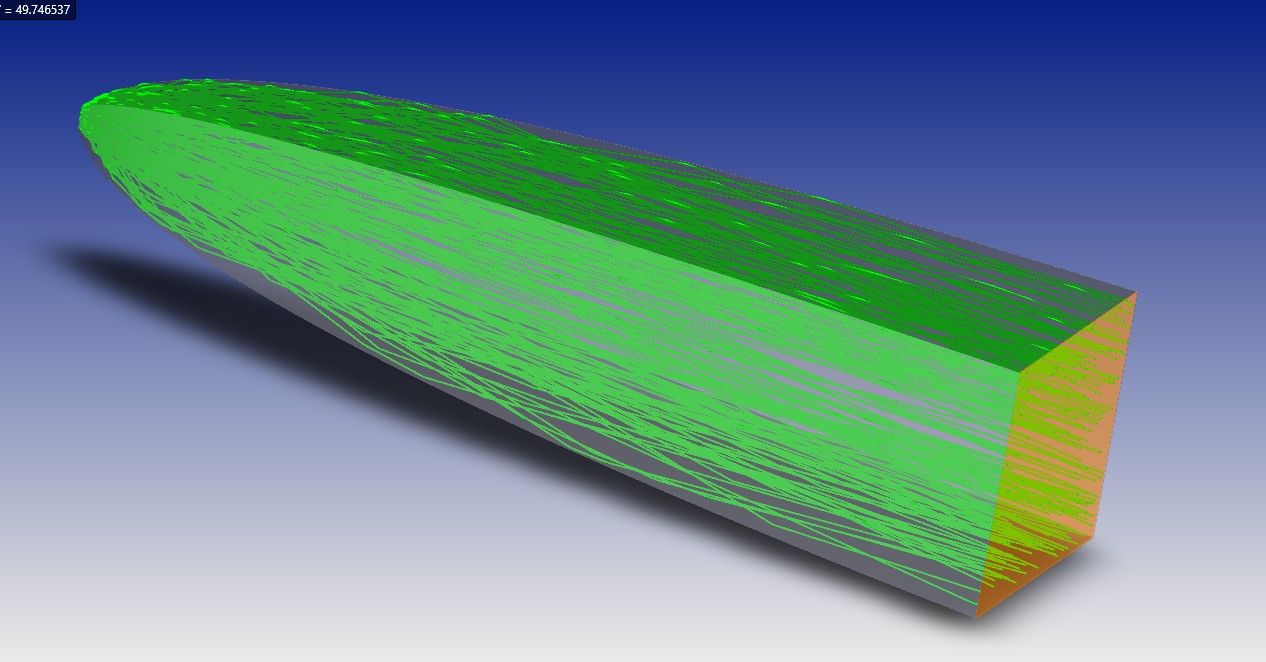
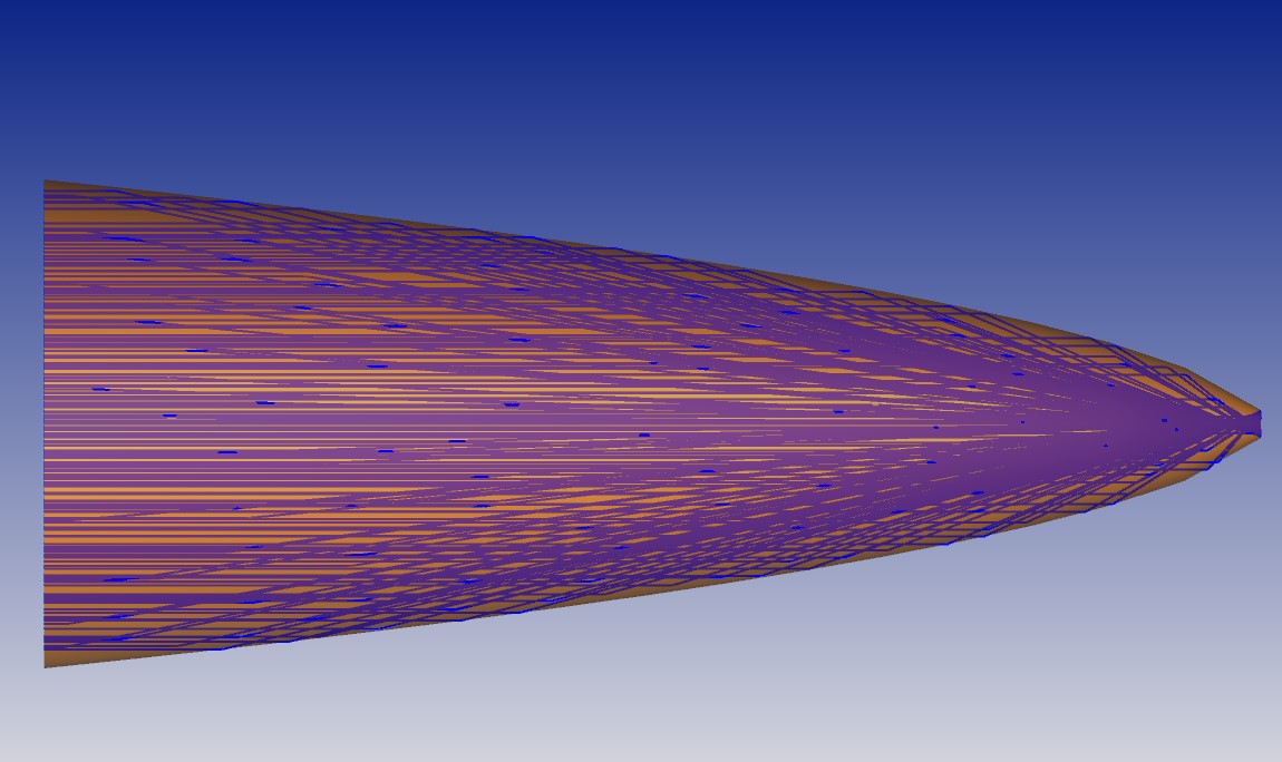
A compound parabolic concentrator (CPC) I designed is shown below. While the two bounding curvatures (top and bottom) are parabolic and mirror images of each other, they’re tilted and meshed together in such a way that the resulting shape is not actually parabolic. The focii of these curves are at two different locations in a plane intersected by the axis of symmetry. That plane is where the CPC optic is truncated and an absorber is placed.
In my example below, the ratio of the entrance area to the exit area is 310x. That’s a reasonable estimate of the concentration ratio one can expect with this CPC, since I designed it to have negligible losses.
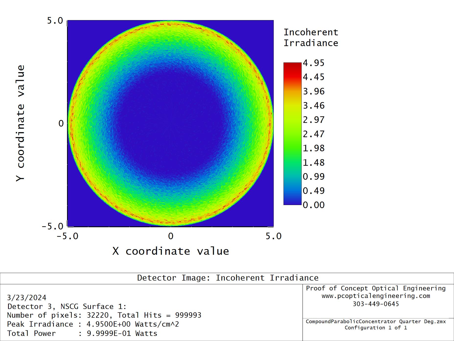
The parabolic focii combine to form a bright ring at the absorber.
The maximum possible concentration is fundamentally limited by a sine law
Cmax=n2/(sin2(θ)),
where theta is the half angle of incident radiation that the CPC can accept and n is the refractive index of the material it’s made of (in the case of a solid CPC).
I designed the previous example for a 0.25-deg acceptance angle (e.g., direct, on-axis solar) and modeled it as a solid with a refractive index of 1.52. Based on those values, the sine law limit is 121,000x, a value unachievable with a CPC. The sine law limit only comes into play when designing for larger acceptance angles.
As the angular acceptance required increases, the concentration ratio that can be achieved with a CPC drops precipitously. For example, a glass CPC designed to accept up to 45 degrees would have, according to the sine law, a maximum possible concentration ratio of only ~5x. So, clearly this is not the best design form for collection over a large field of view.
Much higher solar concentration ratios have been achieved with two-stage concentrators (e.g., two CPCs or other geometries in tandem).
The CPC geometry can also be reversed and used with an LED or LED array for light mixing and collimation. A rectangular shell is a good option for this, since it can be matched to the form factor of a bare LED. It also allows for some independent control of the output ray angles in x and y. However, the output is not spatially uniform.
Below is an example I designed to collimate a lambertian emitter. The concentration value for this reversed geometry is simply the reciprocal of the value determined in the earlier example. The radiance cross sections along x and y are gaussian with half max values corresponding to +/- 5 deg.