Designing Optics for Laser Diodes
Based on my experience designing and selecting COTS optics for laser diode sources, there are several things to consider:
Specification sheets don’t always explicitly provide the information needed to model a laser diode source (e.g., edge emission widths). To the extent that emission from the two axes is gaussian, unknown parameter values can be inferred from the wavelength, far field divergence, and far field relative intensity data.
Performance is temperature-dependent even within the operating range. As temperature increases, more current is required to drive the diode and the emission wavelength increases. Heat sinks, radiators, and active cooling systems are used to mitigate these effects.
Laser diode emission is linearly polarized to an extent that depends on how the diode is driven, among other factors.
The suitability of a particular lens can be checked with a back-of-the-envelope calculation of system etendue.
Lens NA and clear aperture are specified based on the geometric (not the 1/e2) emission from the fast axis. If that’s not practical, diffraction caused by gaussian beam truncation can be accounted for in the model.
If the fast axis NA is large, paraxial gaussian methods won’t accurately represent the beam propagation. However, that inaccuracy is mostly in the tails of the distribution, which in many cases, won’t impact the results significantly. Kirchhoff’s diffraction integrals and physical optics propagation (POP) methods are typically used to model non-paraxial gaussian optics. However, you may find that these scalar diffraction methods are also inaccurate, because the edge emission waist is smaller than the emission wavelength. A more exact method could be used in the near field (e.g., FDTD, plane wave expansion), but since the near field is very close to the emitting edge and the far field divergence is known, fast axis emission can be approximated by a point source and geometrically raytraced to the lens. From there, gaussian optics can be applied with the collimated waist located one focal length after the lens.
The asymmetric output from a laser diode can be circularized with anamorphic lens or prism pairs, passing only the central portion of the beam, coupling in and out of a fiber, or using a spatial filter. A well-designed anamorphic lens pair can achieve a reasonably circular profile with minimal loss.
Below is the physical optics propagation result for a miniature anamorphic lens pair I designed to circularize a laser diode. 16.7 and 33.4 deg were entered as the gaussian emission half-angles for this example. Despite the factor of 2x, the resulting shaped beam profile is fairly symmetric and no power is wasted.

Lasercom Optics
While at Ball Aerospace, I worked on four generations of lasercom programs, first as a stray light analyst and then later, embedded in the TSAT program. I worked closely with the various technical specialists on our team to flow down system requirements and continued to provide optical support throughout the duration of the program, so I’m very familiar with this application.
Lasercom transmitter and receiver optics are designed to first order using methods similar to those used for designing RF antennas. The far field transmit beam profile is shaped by intentional gaussian truncation at the primary mirror. The receive optics are designed to focus a plane wave into an Airy disc, often at the tip of a fiber. Typically, the same telescope is used for both transmitting and receiving. Creative stray light strategies are required to prevent the much higher power transmitted light from contaminating the receive signal.
Laser Beam Expansion and Collimation
Laser beam expanders and collimators are essentially telescopes used in reverse. I use these terms “expander” and “collimator” interchangeably, because the reduction in divergence angle is equal to the increase in beam diameter.
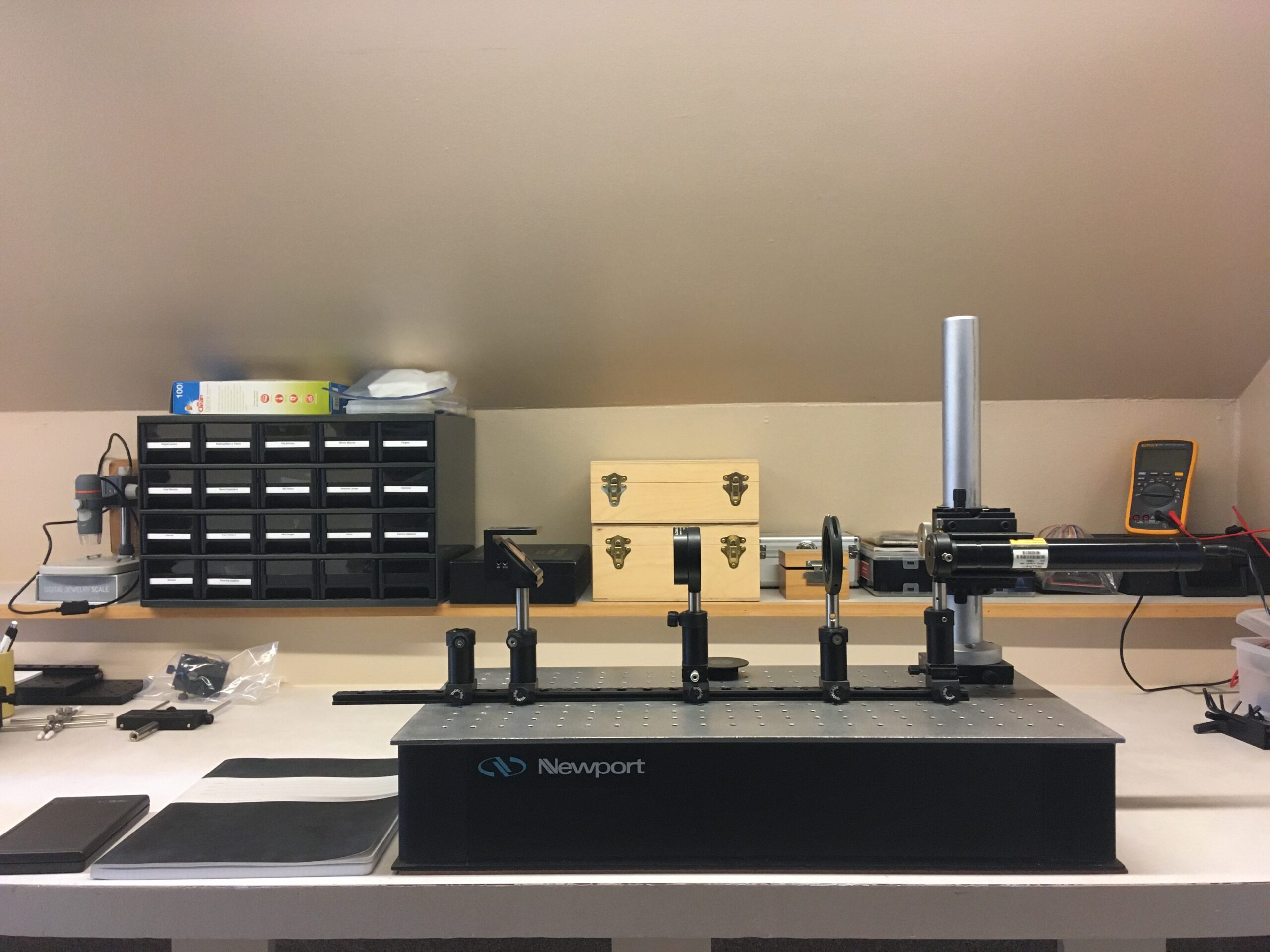
One of the most often used tools in my lab is a 20x Galilean beam expander that I designed for my lab in 2012. I use a shearing interferometer to align it. I later customized this setup for a client who uses it in a microscopy application.
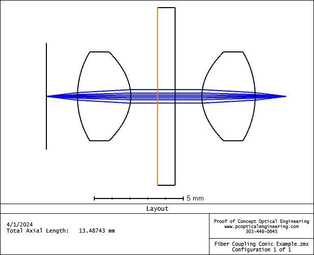
Fiber Coupling
During the telecom boom of the 90’s, I worked on the development of several new products at Wave Optics, including thermally-expanded core fibers and GRIN-coupled fibers.
I still occasionally work with fiber optic systems and select optics for them. Below is an example I created for coupling light from one single-mode fiber into another. This layout makes it possible to incorporate a free-space filter into a fiber optic system. The wavelength is 405-nm and both fibers have an NA of 0.12. I optimized the lens shapes for maximum gaussian coupling efficiency, which was 86% for the front end and 86% for the receiver (for a combined coupling efficiency of 75%). In practice, alignment tolerances would result in a lower coupling efficiency. The impact of tilts and decenters on coupling efficiency can be evaluated fairly easily in Zemax OpticStudio.